Monday, November 22, 2010

Bimini & Heating System

Sunday, Nov 21, 2010
I put up the almost finished bimini.  It looks pretty good.  There are two arches that aren't as tight as I would like them to be, and the front arch is about 2 inches too low.  I can't quite see over the dodger without lifting the fabric up.  Both problems can be fixed without too much difficulty.


Monday, Nov. 22, 2010
I can't believe I spent all day on a 2 hour project (I thought).  All I had to do was replace two 3/4" fitting with 5/8" fittings, drain out the water and replace it with mixed antifreeze.  Of course to get to one of the fittings I had  loosen the octopus by taking 4 screws out.  The screw with the least access was stuck and the top was worn.  When I finally got it out I had to remove two hoses to get the space I needed, so I got them off.  Finally I was able to get a pipe wrench and adjustable wrench on the fittings (I really didn't want to break the fitting off of the octopus.)  After I got them off it was noon.  Then it was four hours mixing antifreeze and pouring it in and trying to get the air out of the system.  But I think it is done.  I think all the air is out of the system.  It's all so mysterious because I can't see what is happening -- occasionally bubbles come up... the level in the expansion tank goes up, then down... doesn't seem to make any sense.
UPDATE: I've been running the pumps for several hours and it is still taking more fluid every half hour or so.  I'll run them all day tomorrow and hope that at some point it stabilizes.  I mean it can't have unlimited volume.  I keep checking for leaks and haven't found anything.

10:00 pm
Well the air finally finished coming out of the heating loops, but the old hose that connected the octopus to the overflow tank cracked.  Of course the size is different from any other hose on the boat, so now I am looking for 5/16" translucent hose that can withstand the heat from the octopus.

Wednesday, 11/24/2010
I mounted the new little pump after testing it to supply raw water to both the galley sink and the shaft seal.  A problem I have been having when sailing fast is that air gets sucked into the shaft seal and without the water it overheats.  I have tried several passive solutions, but none has worked, and some have even made it worse.  In any case this pump will come on when the "water pressure" breaker is on AND either the galley raw water switch OR the "autopilot" breaker is on.  This will be done using a relay with power supplied from the "water pressure" breaker and going either through the galley switch or a normally open relay which is closed when the "autopilot" breaker is on.  With this wiring arrangement the pump will normally be on during sailing, but if we are sailing really slowly and we don't want to hear the vary low vibration of the pump it can be turned off with the "water pressure" breaker.

Saturday, November 13, 2010

Re-bed the Forward Hatch and Test it and the Plumbing

Wow, that hatch was really stuck on.  After about 45 minutes of slicing it with a thin scraper it finally came loose.  The scraper broke several time, and I sharpened it on the sidewalk.  About 40 minutes into it I thought I should have just located the leak and caulk just the leak.  And then it came loose, but it still had vast amounts of caulk stuck to it.  I was pleased to see a discolored section in the corner where it had been leaking.  I decided to be much more discriminating with the caulk, and just caulk the gasket area.  I massaged the caulk into the surface to make sure it was attaching, and then I added a bead on both surfaces and put it together.  A reasonable amount squeezed out all around, and I used most of that coating the screws.  It wasn't as messy as I was afraid it would be.  I changed gloves a lot.
Then I realized I had forgotten the interior insert.  It had also been caulked in place, even though it doesn't have anything to do with waterproofing.  Miraculously it just fit, so I screwed it in place without any caulk so I can inspect the actual waterproofing seal.

Before I did the hatch I finished silicone caulking the hoses, where they go through the bulkheads.  Unfortunately I discovered two holes that needed to be filled with epoxy that I forgot, so I epoxied them.

I also replaced the three cleats for the locking lines that attach to the hatches that open into the cockpit with one larger one.

I figured out where the fuse block could go so that it would be near the battery.  It will really reduce the confusion in the wiring.  I also examined the fittings on the octopus and found that I could replace them with 5/8" connectors.  I'll have to unscrew the octopus, and there is one problem hose that may prevent me from changing it.  In that case I will have to use a hose barb adapter, but that is a bunch more hose clamps.  We'll see.  I ordered both parts.  I studied the circuit diagram and figured out the changes I will have to make.
Original Circuit Diagram
Changes to the circuit diagram
I got the rest of the plumbing hooked up including both the hot glycol plumbing as well as the fresh water.  Strangely enough when I started adding water to the system it was full after only half a gallon -- it should have taken four.  It turned out that I had only drained the circulation lines.  There was another five gallons in the tank for a total of nine gallons in the system.  

It turns out that a circuit diagram is not a wiring diagram.  I've been going nuts trying to figure out exactly which wire goes where so I can change the "domestic hot water" switch over to the "shower glycol pump" and disconnect that pump from working with the shower switch.  I got so burned out working on it I decided to take a break and test the hatch and plumbing system.

I got a hose and sprayed around the hatch for about five minutes -- Ta Da -- No Leak.  Then I put water in one of the tanks and turned on the fresh water pump.  It was like a fountain under the sink.  I forgot to put one of the hose clamps on, but that didn't fix it.  The selection valve was leaking.  I discovered that the back screws were loose, but when I tightened them up, while it stopped the leak, it was very difficult to turn.  Fortunately there is a "sweet spot" where it doesn't leak and is easy to turn.  The only other problem was leaking from the cold water sink foot pump.  It was leaking around the adapters for the hose.  I took them out and put Teflon tape around the threads, but that didn't work completely.  It turned out that when the hose clamps were tightened it was putting lateral stress on the fittings which was causing the leak.  I re-installed it with a little more play and the leak didn't come back.
The simplified plumbing system in the engine room.  The heat exchanger is located under the shelf.  The red and black hoses are for the glycol circulation.  The silver hoses are for the fresh water.  The brass valve in the wall is the mixer.

Monday, November 8, 2010

Plumbing and Holes II

I got the air intake baffel epoxy coated and the large holes from the moved heater hoses as well as the little screw holes in the motor base filled.

PolarPower got the genset over to SoundWaves for the sound shield.  The original plan was that they would just make a pattern, I would get the genset and then after I installed it I would mark the pattern and they would make it up and send it to me.  However that can't happen because PolarPower needs the sound shield so they can test the genset inside it to see if it overheats.  So now I have to specify where all the hoses will exit the sound shield before I even see the engine let alone fit it into its space.  So I've  been analyzing the instructions and trying to diagram them over pictures of the genset from PolarPower and the instruction manual.
It turns out that because of the location of the generator to the water line and the heater circuit every hose that could need to exit the motor compartment and be mounted to a bulkhead needs to be installed.  If the genset were raised 9", then none of the hoses would need to be installed.  But of course it can't be raised the 9".  So now I somehow need to communicate with SoundWaves the locations of the openings for the hoses.
Tuesday 11/9/10
I sanded the baffle to smooth all the epoxy bumps off.  Then I cut out all the extra wood that used to support the edge of the cover (that the mattress rests on).  I used a "Multi Max" that vibrates a blade and it cuts through the wood slowly but surely.  So I sculpted some grooves for the angle bar to fit into making it much stronger than my original plan where the angle bar was only supported by being part of the 1/4" plywood baffle.

Then I screwed everything together and took my final measurements for the cut to remove a corner of the cover so it would fit snuggly next to the baffle.  Hay - it worked.  So everything fits and is very strong.


After I got all raw wood epoxy coated I started work on the plumbing.  I had to drill another hole from the galley  (behind the drawers under the sink) to implement the new plan for actually  having hot water in the galley sink.  I epoxy coated it with the other stuff.


I also finished up the plumbing under the head sink.  The fresh water comes in via a pump and then goes to a heat exchanger, thermostatic valve, and a diverter valve for the hose source.  The hot water also goes to the thermostatic valve.  From there the mixed water goes to the sprayer and the hose source valve.  Finally either mixed or cold leaves the diverter valve and goes both the the hose bib and the hose that lives under the sink.

Friday, November 5, 2010

Lots of picky stuff, but no visible progress


This trip didn't start out so well.  I was going to test the new bimini, but in the rush to finish I forgot to put the new side panels on it, effectively making a new bimini with just the old design.  It fit nicely, but I took it down and put it in the car so I wouldn't get annoyed when I saw it.
Rain was coming, so I got out the big tarp and put it over the boom covering the whole cockpit and half of the cabin.  I tied it in a new way, and it fits quite well.

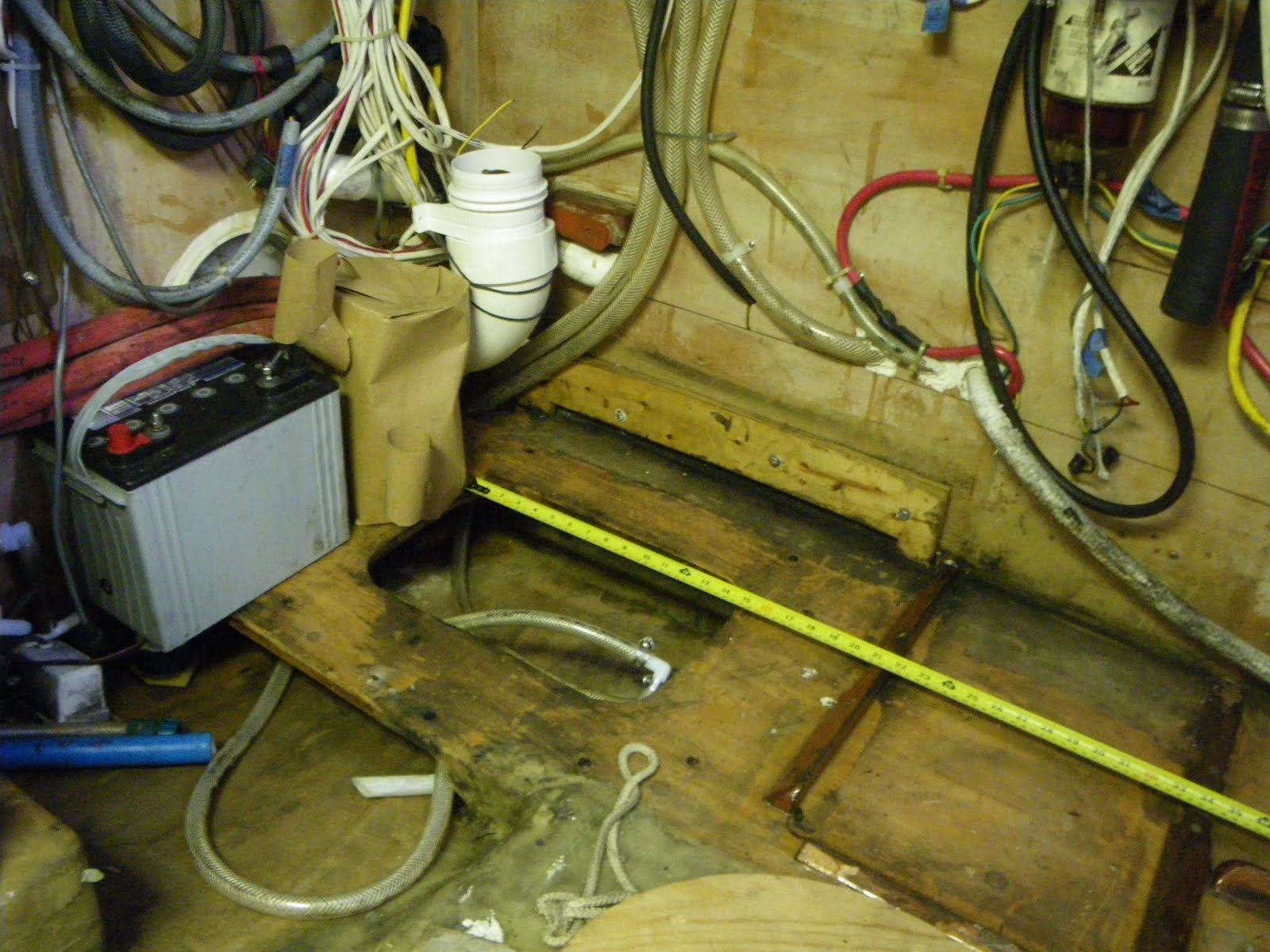
The wood cleats that held the battery and fuel tank needed to be removed because the battery is moving forward and the fuel tank is moving aft 10 inches.  They were screwed and epoxied to the sole.  I used a chisel to break them loose and break them away from the screws which were epoxied into their holes.  Next I took one of those little torches and heated the screws to soften the epoxy so I could turn them out with a vice-grip.

This is before I removed the wooden cleats (on right) and realized
the hoses were in the way of the fan (left rear).
Next I started to grind the remainder with the belt sander, but the switch failed and it wouldn't turn on, so I switched to my 4" grinder which finished the job in just a few minutes - boy that tool cuts fast with a 36 grit wheel.

I plan to mount the vent fan that sucks air out of the motor compartment and blows it into the engine room in a 6" PVC elbow.  It turns out that the three heater hoses cover the exact location where the hole into the motor compartment must go (naturally).  So I detached the ends of the hoses and drained 4 gallons of old antifreeze and pulled the hoses out of the way so I could drill new holes under the sole routing the hoses under the genset instead of against the bulkhead.

I spent the rest of the day cleaning out the old holes, filling them with epoxy and drilling new holes for the relocated heater hoses.
Note how the holes are behind the shaft making tool access difficult.

Close up of the new holes and a filled hole.

The bad news from the day is that the brackets I made for the heat exchanger will be impossible to install without removing the "octopus" (which is the hot glycol storage tank), and  they also need to to be bent somewhat differently.  It's too bad because it could have worked nicely.
Friday:
I spent most of the morning replacing the mocked-up plumbing in the head with the real thing.  There are more than 40 hose clamps under the sink.  Next I installed the fan vent from the motor enclosure into the engine room.  I used my new cut-out tool and it burned its way slowly around most of the circle, and I finished it off with a hand saw.  Then I was looking at the heat exchanger bracket and decided that I could epoxy the ends of a rail against the underside of the shelf so that in the middle, the top of the rail is 1/8 inch below the underside of the shelf where the heat exchanger is going such that the brackets can slide in the slot between the rail and shelf.  That will hold the back ends of the brackets, and I can screw in the front easily.  Finally I designed the vent in the quarter berth.  It is simply a wall that cuts a long skinny triangle out of the bunk for an air intake chase.  It is tucked way up in the forward corner and is 24" long and tapers from 5" to nothing and rises to about an inch from the ceiling.

The boat is a mess to say the least since everything had to be pulled out of the way to do the work.  But the worst part is that all the hose holes that aren't sealed up create a situation where water can leak from the shaft compartment into the engine room and main cabin -- it's never leaked, but is the most vulnerable spot, and now it isn't isolated from the rest of the boat like it usually is.  By the time it leaked an inch into the main cabin there should be three bilge pumps going.